Guition JC-ESP32P4-M3-DEV
This board features a Guition JC-ESP32P4-M3, which is a module that includes an ESP32-P4 and an ESP32-C6 as a co-processor for WIFI/Bluetooth.
Links
- Official Sales Page
- Board Description
- ESP32-P4 Datasheet
- ESP32-P4 Technical Reference
- ESP32-C6 Datasheet
- ESP32-C6 Technical Reference
Github Repos
- https://github.com/DRubioG/JC-ESP32P4-M3-DEV (Unofficial Schematics)
- https://github.com/p1ngb4ck/unofficial_guition_esp32p4_repo/tree/main/JC-ESP32P4-M3-Dev (Unofficial Schematics with other documents)
Board Connectors
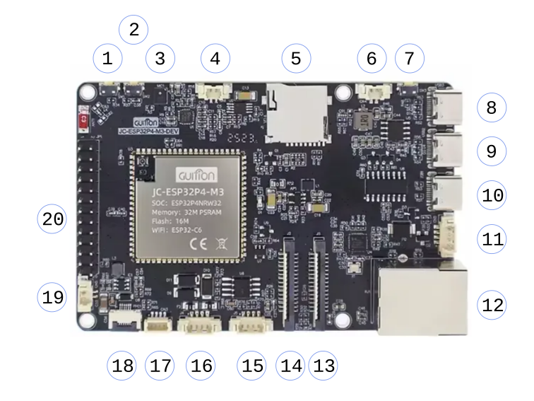
| Symbol | Description |
|---|---|
| 1 | BOOT (SW1) - Boot Mode/GPIO35 |
| 2 | RESET (SW2) - CHIP_PU |
| 3 | Microphone (MIC1) |
| 4 | Speaker (CN1) |
| 5 | microSD Card Reader (J1) |
| 6 | Battery Connector (CN4) |
| 7 | Battery Start Charging (SW3) |
| 8 | USB High Speed (USB3) |
| 9 | USB Full Speed (USB2) |
| 10 | USB TTL/UART (USB1) |
| 11 | MX1.25 4P Power Input (CN2) |
| 12 | Ethernet (RJ1) |
| 13 | Camera CSI (J3) |
| 14 | Display DSI (J2) |
| 15 | MX1.25 4P RS485/RS422 Input (J5) |
| 16 | MX1.25 4P RS485/RS422 Driver Output (J4) |
| 17 | JST SH1.0 4P I2C (CN3) |
| 18 | FPC Capacitive Touch 6pin 0.5mm (FPC1) |
| 19 | Backlight LED Output (CN5) |
| 20 | Expansion IO (JP1) |
Inputs and Connectors
Microphone
MIC1 connects to DAC chip
Speaker
DAC Chip is connected to NS4150 (Audio Amplifier), which can be enabled by setting GPIO11 to HIGH.
DAC Chip
ES8311 Chip ADC for input (MIC) and DAC for output.
Control through I2C using GPIO7 (SDA) and GPIO8 (SCL) and an address of 0x18 (7 bit, or 0x30 for 8 bit address).
Data through I2S needs:
| GPIO | I2S Config |
|---|---|
GPIO13 | mclk |
GPIO12 | bclk |
GPIO10 | ws |
GPIO9 | dout (Speaker) |
GPIO48 | din (Mic) |
Links
- ES8311 Datasheet
- ES8311 User Guide
- I2S ESP-IDF Reference
- Example - Output audio
- Examples - Record from mic and echo
microSD Card Reader
| GPIO | Description |
|---|---|
GPIO45 | Enable (Power TF Card) |
GPIO43 | CLK |
GPIO44 | CMD |
GPIO39 | DATA0 |
GPIO40 | DATA1 |
GPIO41 | DATA2 |
GPIO42 | CD/DATA3 |
MX1.25 Power Input (CN2)
CN2 is a 4-pin Power Input and UART, pins:
| PIN | Description |
|---|---|
| 1 | 5V Power |
| 2 | UART TX (GPIO37) |
| 3 | UART RX (GPIO38) |
| 4 | GND |
Ethernet
JST SH1.0mm 4P I2C (CN3)
4 Pin interface for I2C Communication
| PIN | Description |
|---|---|
| 1 | GND |
| 2 | 3.3V Power |
| 3 | SCL (GPIO8) |
| 4 | SDA (GPIO7) |
MX1.25 4P RS485/RS422 (J5 Input, J4 Output)
Uses a MAX485 to handle input and send output
Input (J5)
| PIN | Description |
|---|---|
| 1 | 5V Power |
| 2 | R Receiver Output |
| 3 | D Driver Input |
| 4 | GND |
Output (J4)
| PIN | Description |
|---|---|
| 1 | 5V Power |
| 2 | A Noninverting Driver Output |
| 3 | B Inverting Driver Output |
| 4 | GND |
To enable it, UART must be used through GPIO27 (RX/R) and GPIO26 (TX/D).
Backlight LED Output (CN5)
It uses an MP3202 to power up to 39 white LEDs.
To enable the chip, GPIO23 must be used.
| PIN | Description |
|---|---|
| 1 | Top / Cathode |
| 2 | Bottom / Anode |
| 3 | GND |
| 4 | GND |
FPC Capacitive Touch 6pin 0.5mm (FPC1)
| PIN | Description |
|---|---|
| 1 | 3.3V Power |
| 2 | GND |
| 3 | SDA (GPIO7) |
| 4 | SCL (GPIO8) |
| 5 | INT |
| 6 | RST |
Expansion IO (JP1)
| PIN | Description |
|---|---|
| 1 | 3.3V Power |
| 2 | 5V Power |
| 3 | 3.3V Power |
| 4 | 5V Power |
| 5 | GND |
| 6 | GND |
| 7 | GPIO1 |
| 8 | NC |
| 9 | GPIO2 |
| 10 | GPIO47 |
| 11 | GPIO3 |
| 12 | GPIO46 |
| 13 | GPIO4 |
| 14 | GPIO45 |
| 15 | GPIO5 |
| 16 | GND |
| 17 | GPIO20 |
| 18 | 3.3V Power |
| 19 | GPIO32 |
| 20 | C6_U0RXD (C6 RX) |
| 21 | GPIO33 |
| 22 | C6_U0TXD (C6 TX) |
| 23 | SDA |
| 24 | C6_IO9 (C6 BOOT) |
| 25 | SCL |
| 26 | C6_CHIP_PU (C6 RESET) |
Setup
VSCode
- Install Extension
- Select
ESP-IDF: Explorersidebar Advanced -> New Project Wizard- Select SDK Version
ESP-IDF Templates -> sample_projectclick on buttonCreate project using template sample_projectand select location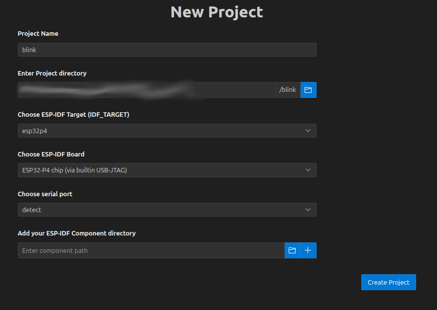
- Select Command
SDK Configuration Editor (menuconfig) - Select
Component config -> Hardware Settings -> Chip Revision - Check
Select ESP32-P4 revisions <3.0 (No >=3.x Support) Minimum Supported ESP32-P4 RevisionselectRev v1.0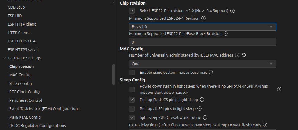
Build ProjectFlash DeviceselectUART
The led (with resistance) should be connected to GND (JP1 Pin 5) and GPIO1 (JP1 Pin 7) and should blink each second.
main/main.c
#include <stdio.h>
#include "freertos/FreeRTOS.h"
#include "freertos/task.h"
#include "driver/gpio.h"
#include "esp_log.h"

#define BLINK_GPIO GPIO_NUM_1
#define BLINK_PERIOD 1000

static const char *TAG = "blink";
static uint8_t s_led_state = 0;

static void blink_led(void)
{
    /* Set the GPIO level according to the state (LOW or HIGH)*/
    gpio_set_level(BLINK_GPIO, s_led_state);
}

static void configure_led(void)
{
    ESP_LOGI(TAG, "Example configured to blink GPIO LED!");
    gpio_reset_pin(BLINK_GPIO);
    /* Set the GPIO as a push/pull output */
    gpio_set_direction(BLINK_GPIO, GPIO_MODE_OUTPUT);
}

void app_main(void)
{
    /* Configure the peripheral according to the LED type */
    configure_led();

    while (1) {
        ESP_LOGI(TAG, "Turning the LED %s!", s_led_state == true ? "ON" : "OFF");
        blink_led();
        /* Toggle the LED state */
        s_led_state = !s_led_state;
        vTaskDelay(BLINK_PERIOD / portTICK_PERIOD_MS);
    }
}
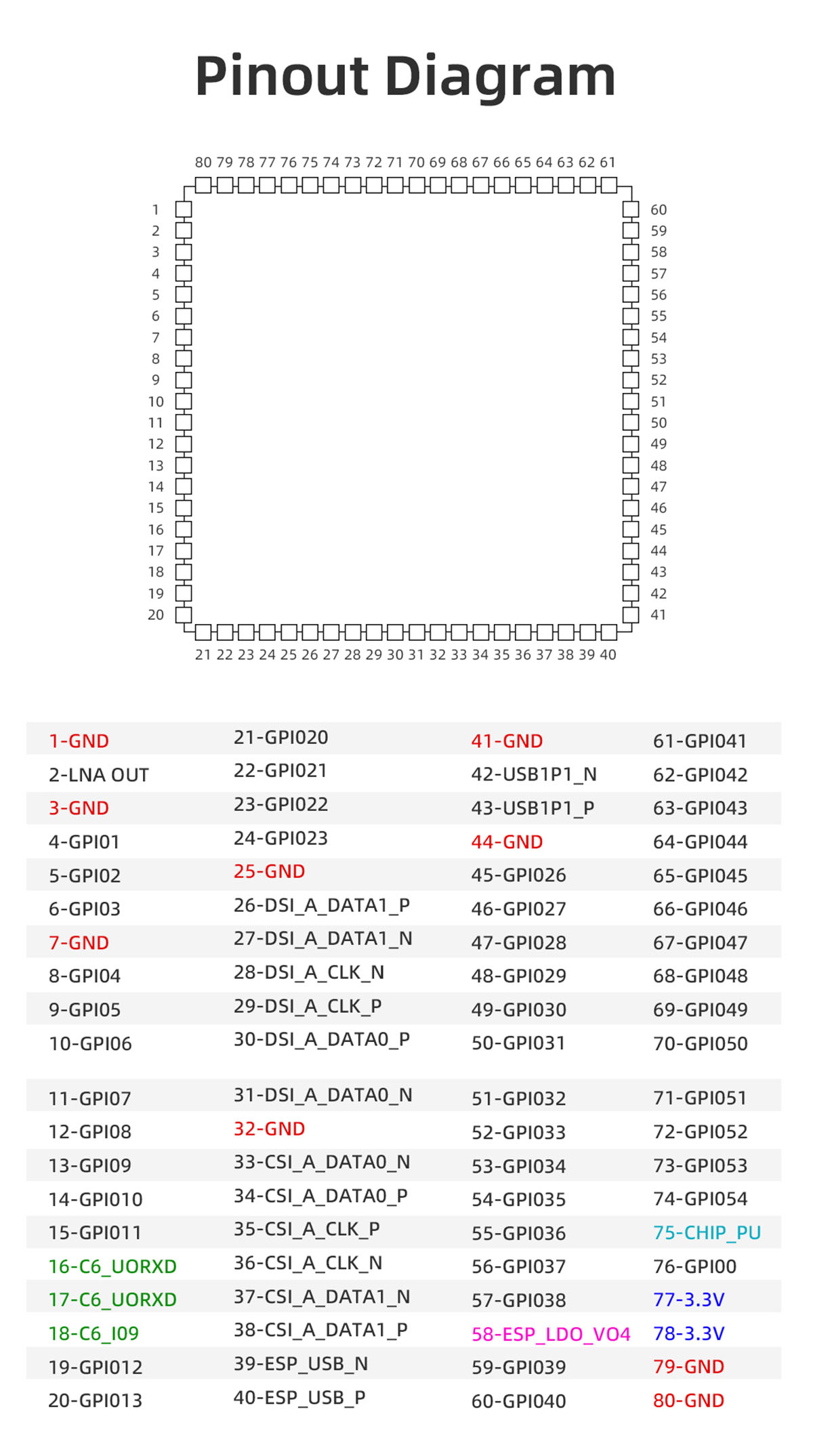
Module Pinout